Lift Plan Drawing Examples
Example lift plan drawings from RMT Solutions for mobile cranes, excavators, steel erection, lorry loaders and telehandlers. Each set shows the elevation, the exclusion zone plan and the rigging drawing a lift team is briefed from, drawn to the machine's real dimensions and the planned lift.
A good lift plan drawing answers the questions a site manager, slinger and operator will ask: where the machine stands, how far it reaches, how high the boom goes, where the barrier runs, who stands where and exactly what is under the hook. The figures on every sheet (radius, gross load, capacity and utilisation) come from the manufacturer's own duty chart, and the gross load includes the rigging, the hook block or the quick hitch.
RMT drawing examples
Mobile crane lift plan drawings
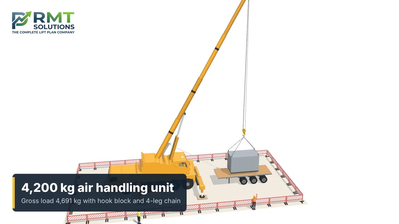
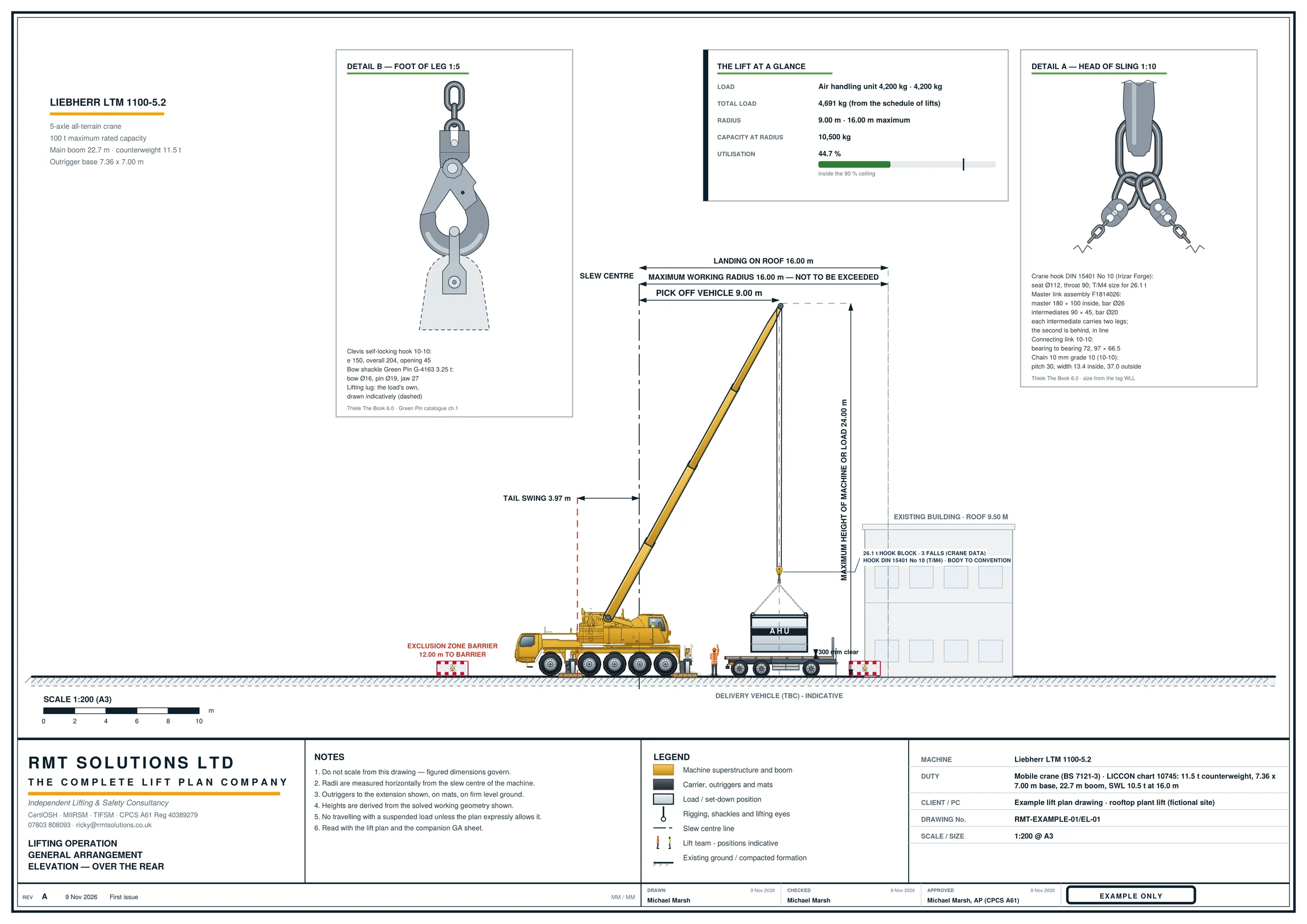
This example shows a Liebherr LTM 1100-5.2 all-terrain crane lifting a 4,200 kg air handling unit off a delivery vehicle and landing it on a roof 9.5 m up. The crane works over the rear on a 7.36 x 7.00 m outrigger base with 11.5 t counterweight and a 22.7 m boom. The gross load of 4,691 kg includes the hook block and the 4-leg chain, read against 10.5 t on the Liebherr chart at 16 m: 44.7% utilisation.
Mobile crane lift plan elevation
The side elevation shows the crane, the pick off the vehicle at 9.0 m, the landing on the roof at 16.0 m, the boom, hook block and rigging, the maximum height and the tail swing.
Open full-size drawing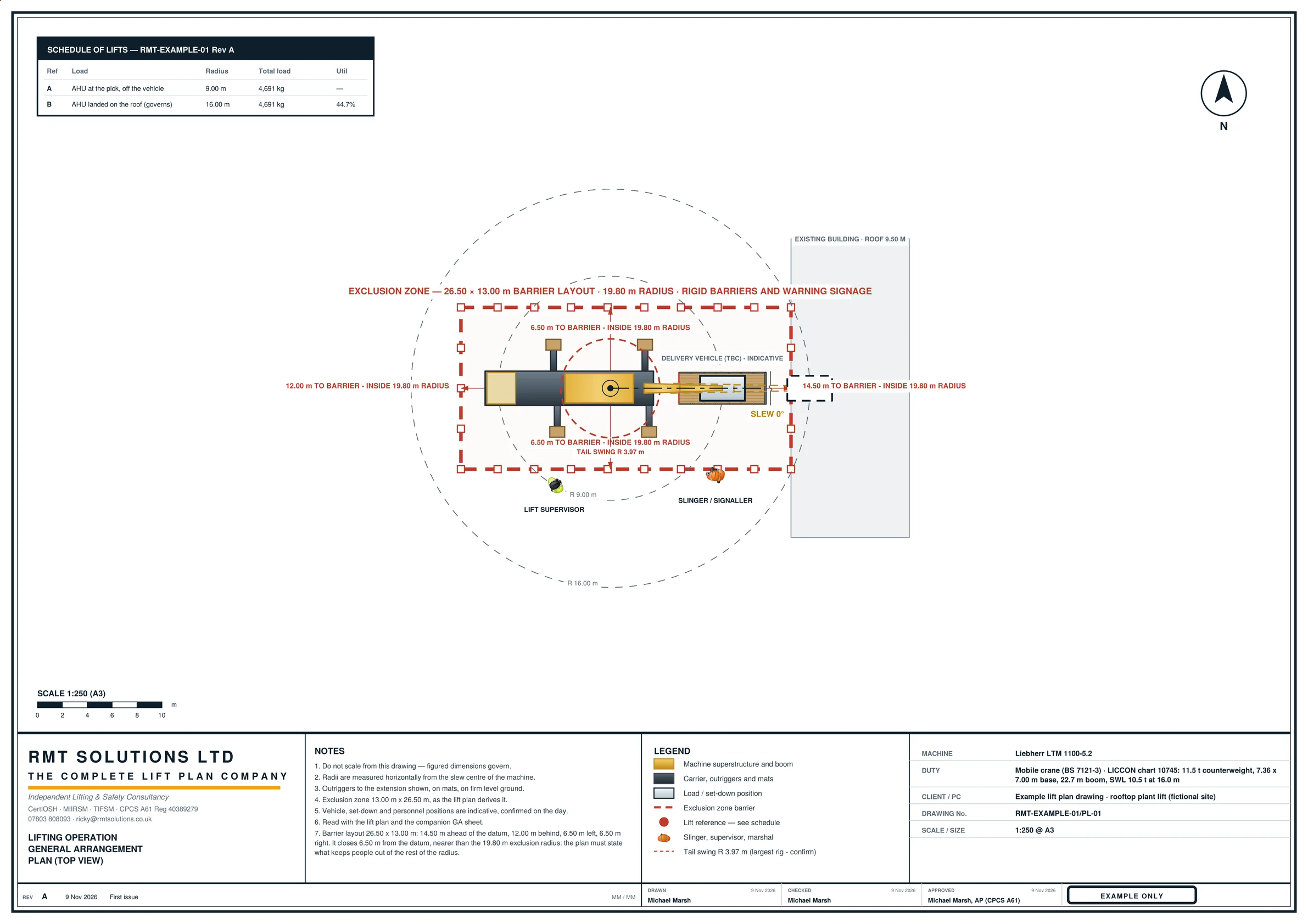
Mobile crane exclusion zone plan
The plan view shows the outrigger base and mats, the tail swing, the working radius, the barrier layout closing on the building face and the lift team positions.
Open full-size drawing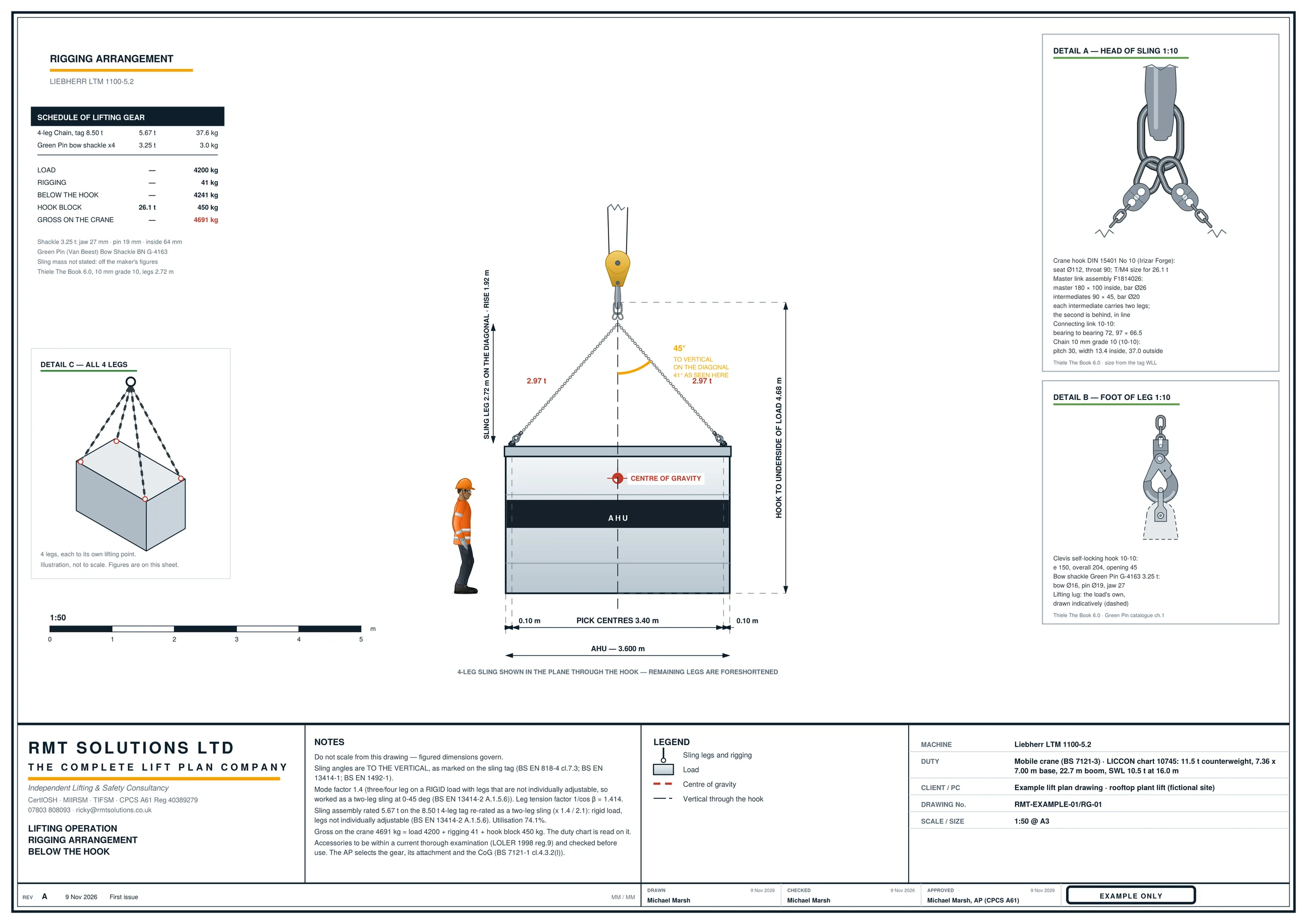
Mobile crane rigging drawing: 4-leg chain
The rigging sheet shows the hook block, master link, 4-leg grade 10 chain at 45 degrees, the leg tensions and the gross load including the hook block.
Open full-size drawingThese anonymised drawings show examples of RMT drawing presentation. They are not site instructions or approved plans for another lift. Each operation requires a plan for the actual equipment, load and site conditions.
RMT drawing examples
Excavator lift plan drawings: manhole chamber ring
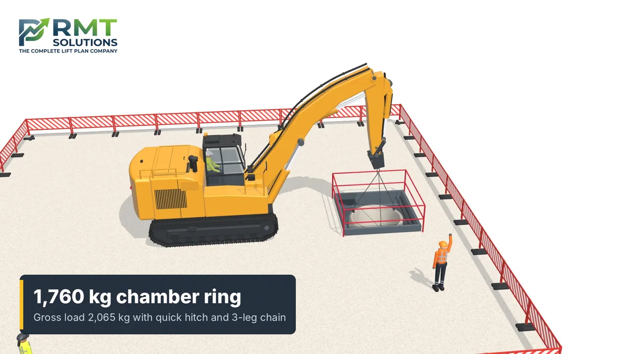
This example shows a Cat 320 GC excavator lowering a Marshalls DN1800 x 1000 chamber ring (1,760 kg) into a supported excavation, lifting from the quick hitch lifting eye with the bucket off. The gross load of 2,065 kg includes the 290 kg quick hitch and the 3-leg chain, read against 4,850 kg on the Caterpillar chart at 6.0 m: 42.6% utilisation.
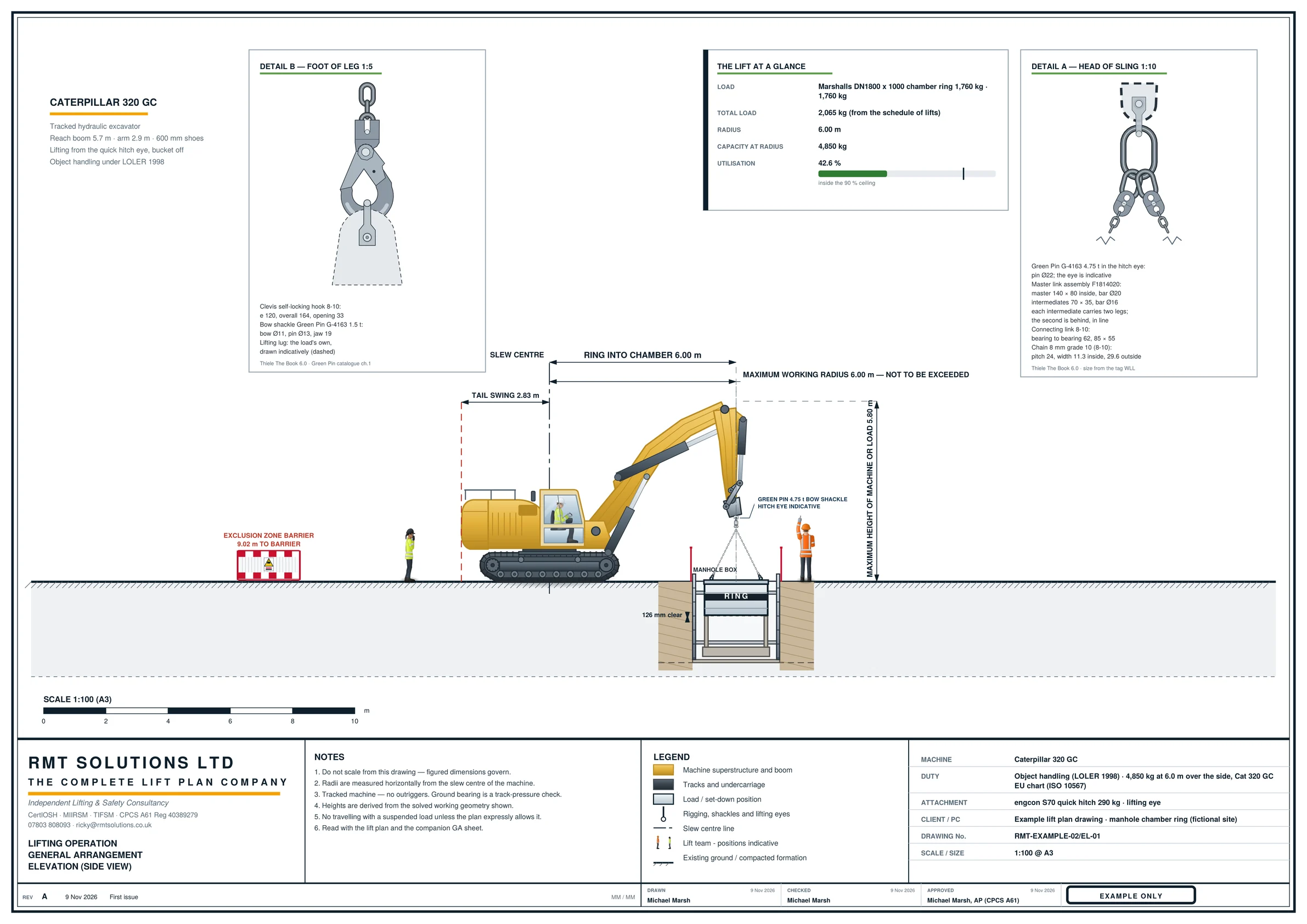
Excavator lift plan elevation: chamber ring into a manhole box
The side elevation shows the Cat 320 GC at 6.0 m radius lowering the ring into the manhole box, with the tail swing, the maximum height of 6.35 m, the lift team and the exclusion zone barrier.
Open full-size drawing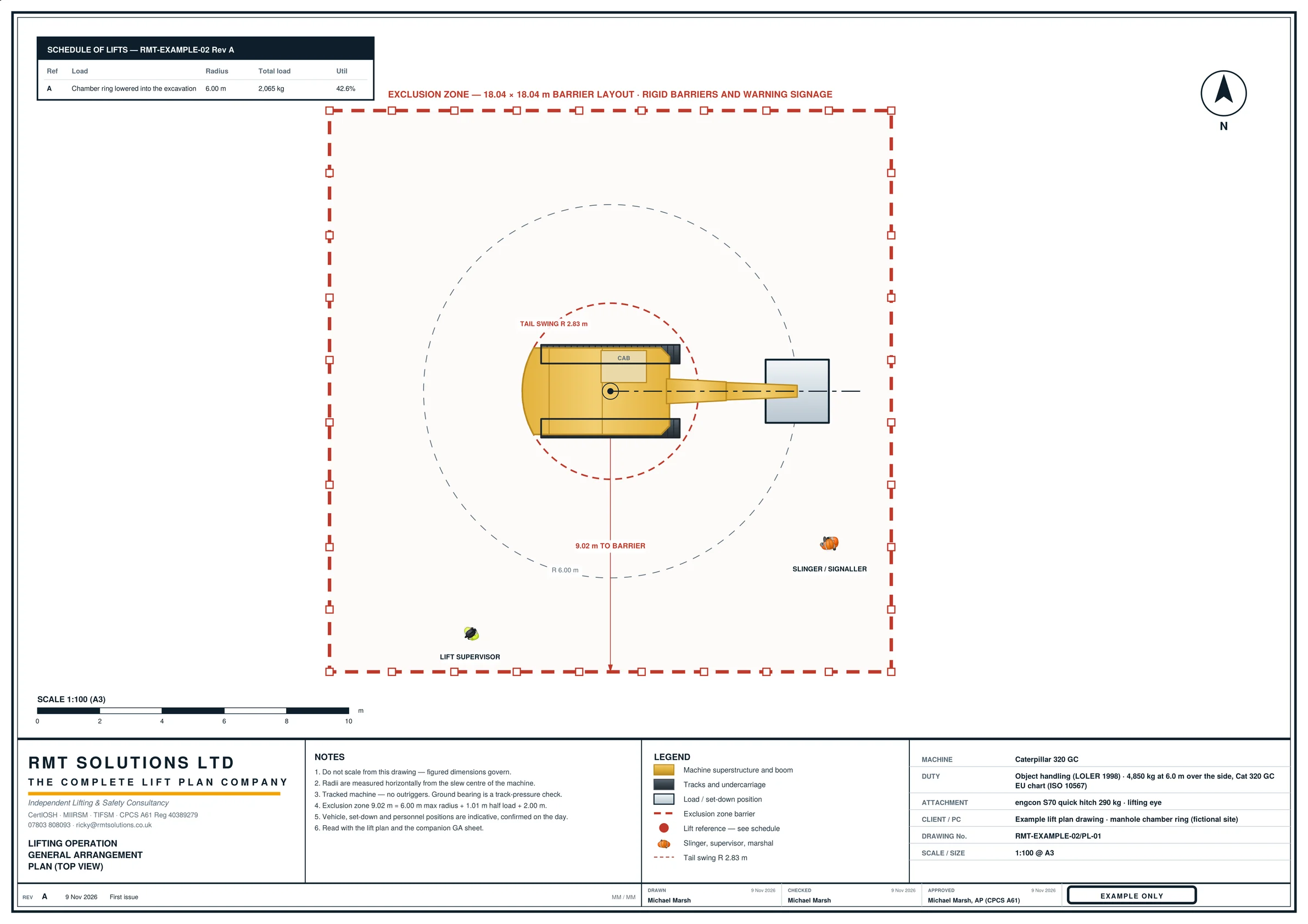
Excavator exclusion zone plan
The plan view shows the tail swing radius, the working radius, the square barrier layout and where the slinger and lift supervisor stand.
Open full-size drawing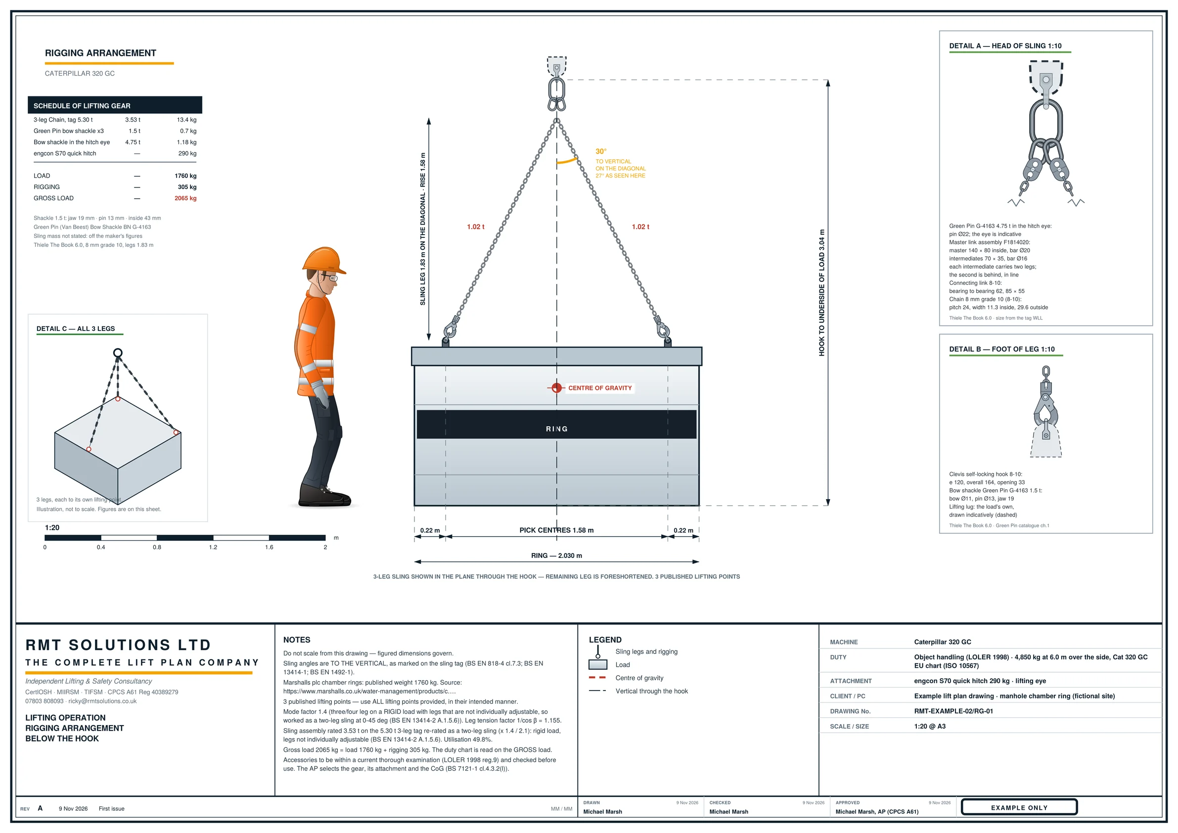
Chamber ring rigging drawing: 3-leg chain
The rigging sheet lists every item of lifting gear with its rating and mass, the leg tension, the sling angle and the gross load the duty chart is read against.
Open full-size drawing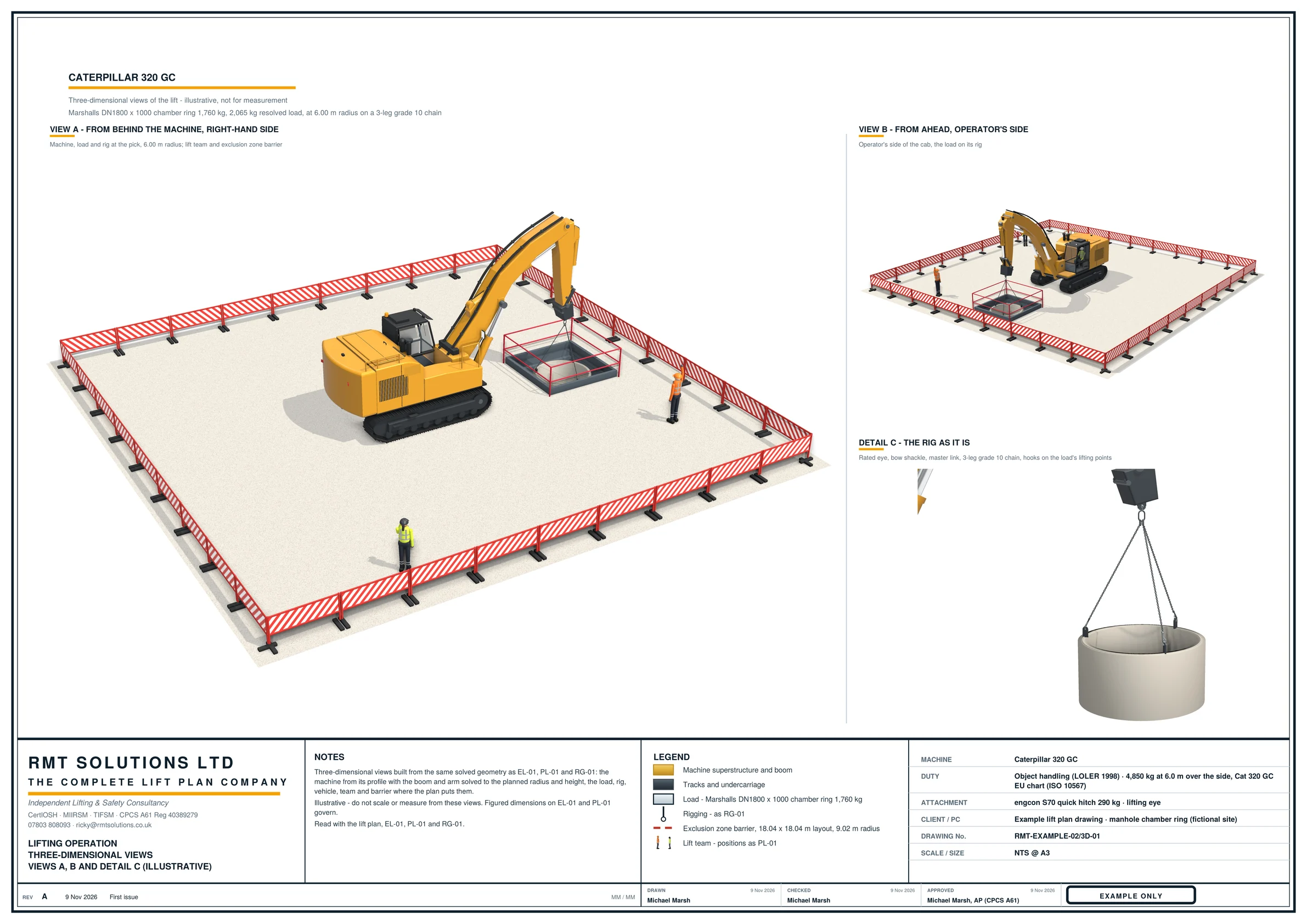
Excavator lift plan 3D views
Three-dimensional views of the same lift: the machine, the ring going into the manhole box with its edge protection, the exclusion zone and a close-up of the rig.
Open full-size drawingThese anonymised drawings show examples of RMT drawing presentation. They are not site instructions or approved plans for another lift. Each operation requires a plan for the actual equipment, load and site conditions.
RMT drawing examples
Excavator lift plan drawings
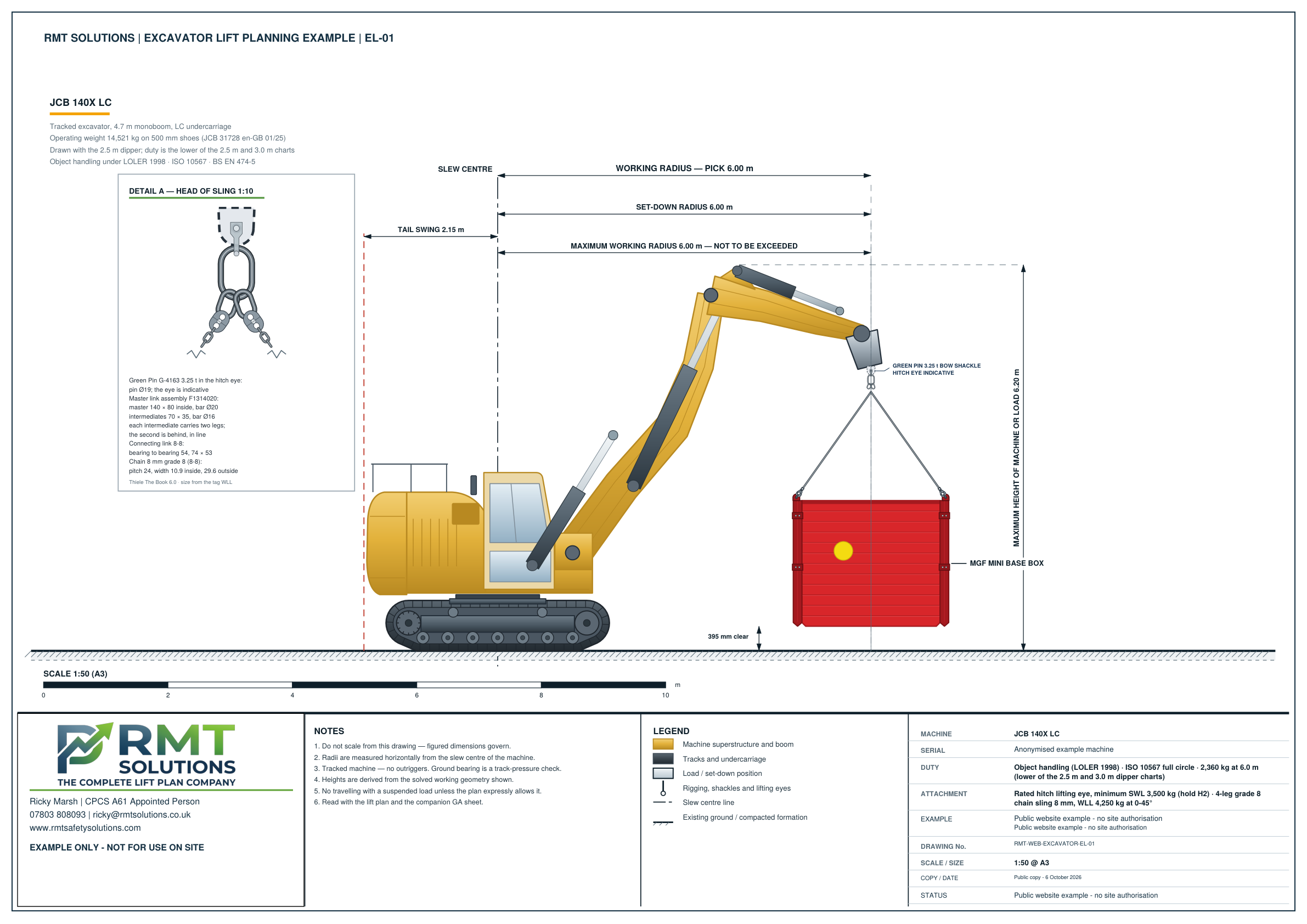
This JCB 140X LC example illustrates the proposed lifting arrangement for a trench box. The elevation, plan view and rigging detail communicate different parts of the operation: machine and load position, working area and exclusion zone, and the connection between the load and lifting accessories.
JCB 140X lifting elevation
The side elevation shows the proposed excavator and trench-box arrangement, with the lifting geometry presented alongside the load.
Open full-size drawing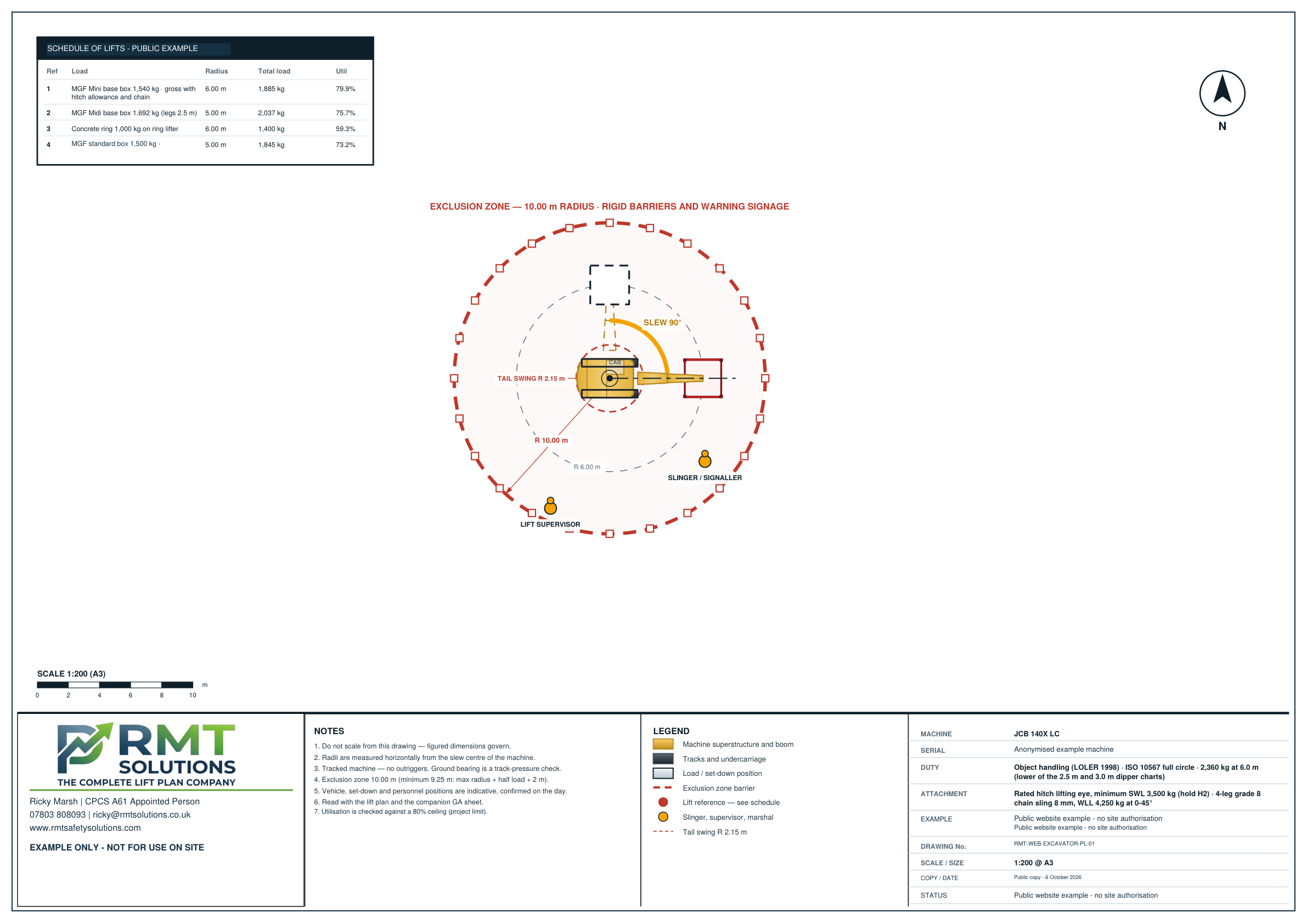
Working area and exclusion zone
The plan view shows the proposed working area and exclusion zone in relation to the excavator and lifting operation.
Open full-size drawing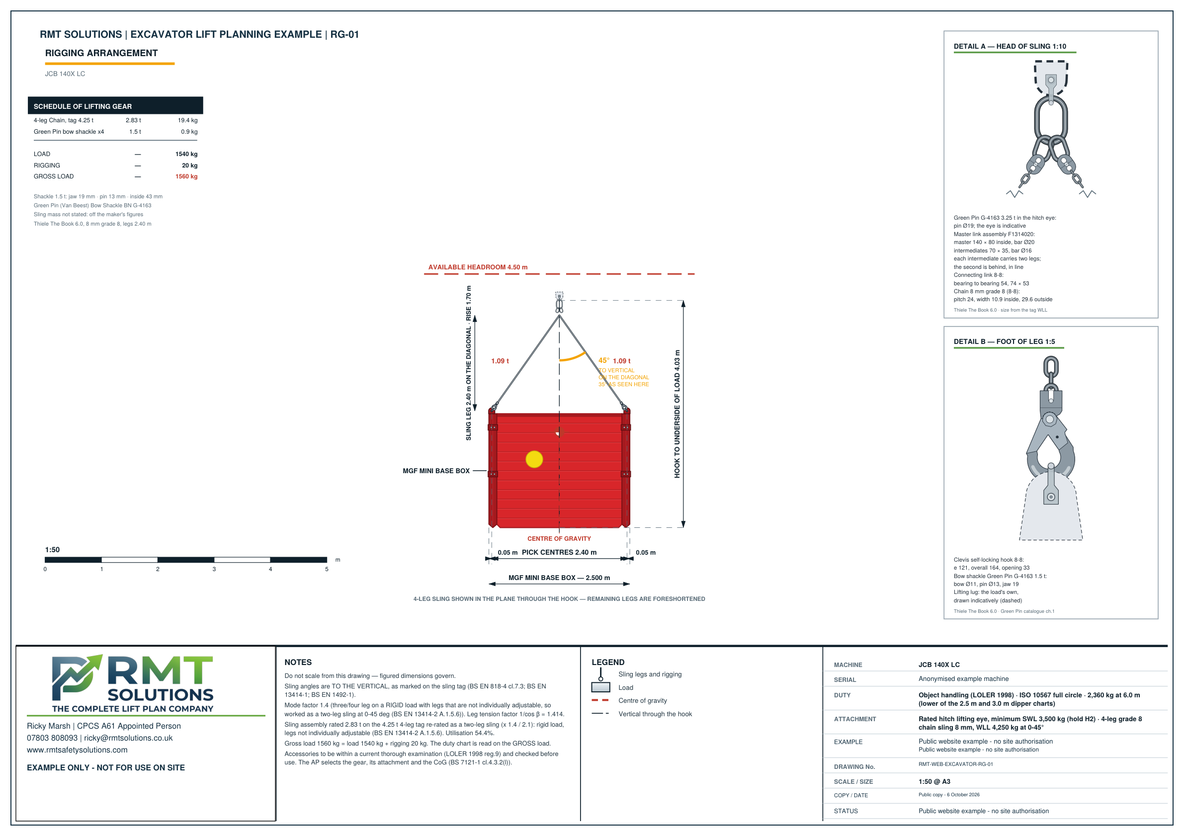
Trench-box rigging detail
The rigging detail sets out the proposed lifting accessories and connections for the trench-box load.
Open full-size drawingThese anonymised drawings show examples of RMT drawing presentation. They are not site instructions or approved plans for another lift. Each operation requires a plan for the actual equipment, load and site conditions.
RMT drawing examples
Steel erection lift plan drawings
These steel erection planning drawings show how the crane arrangement, steelwork geometry and rigging details can be brought together in a clear drawing package. The different views help the lifting team understand the proposed operation and the relationship between the crane, load and structure.
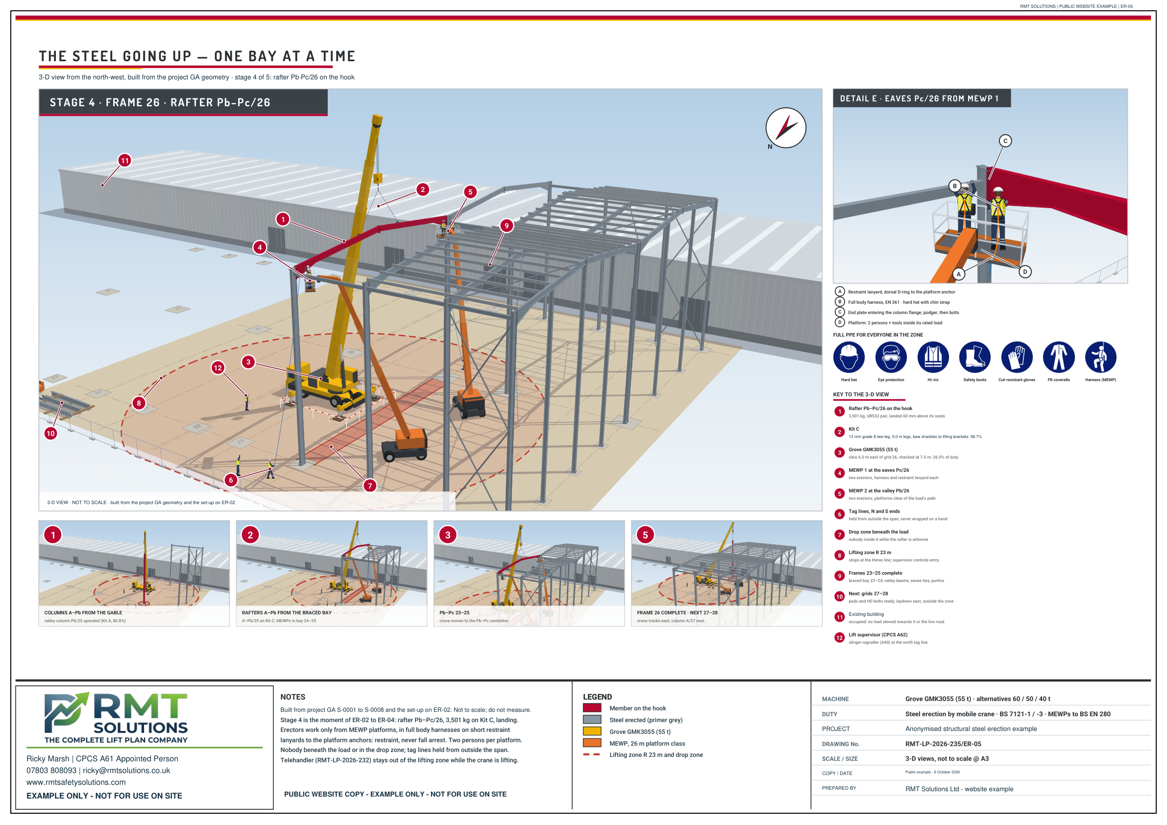
Steel erection lifting arrangement
A three-dimensional view of the proposed crane and steelwork arrangement, helping the team visualise the lift within the building frame.
Open full-size drawing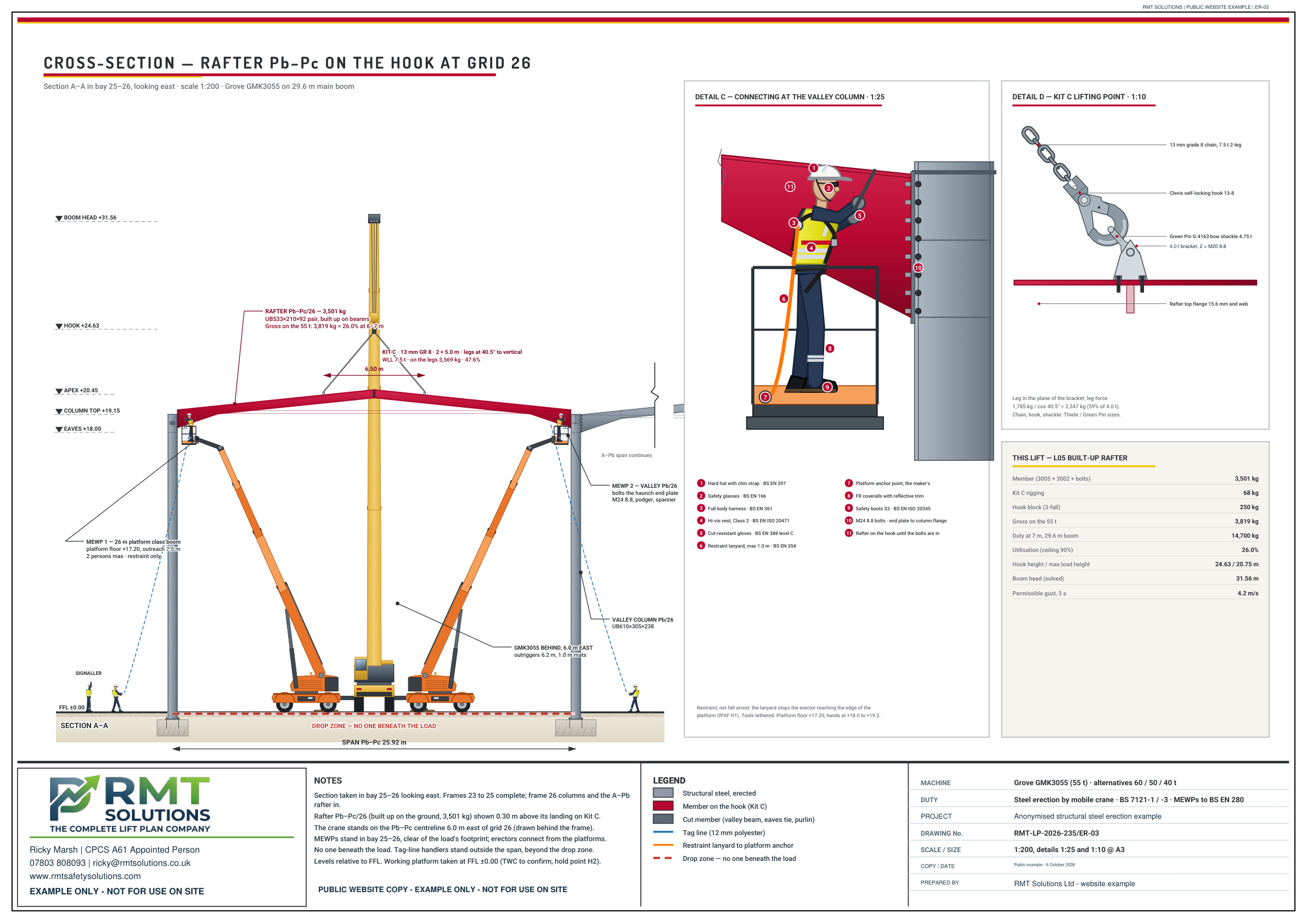
Structural cross-section
A section view showing the relationship between the proposed lifting arrangement and the steel structure.
Open full-size drawing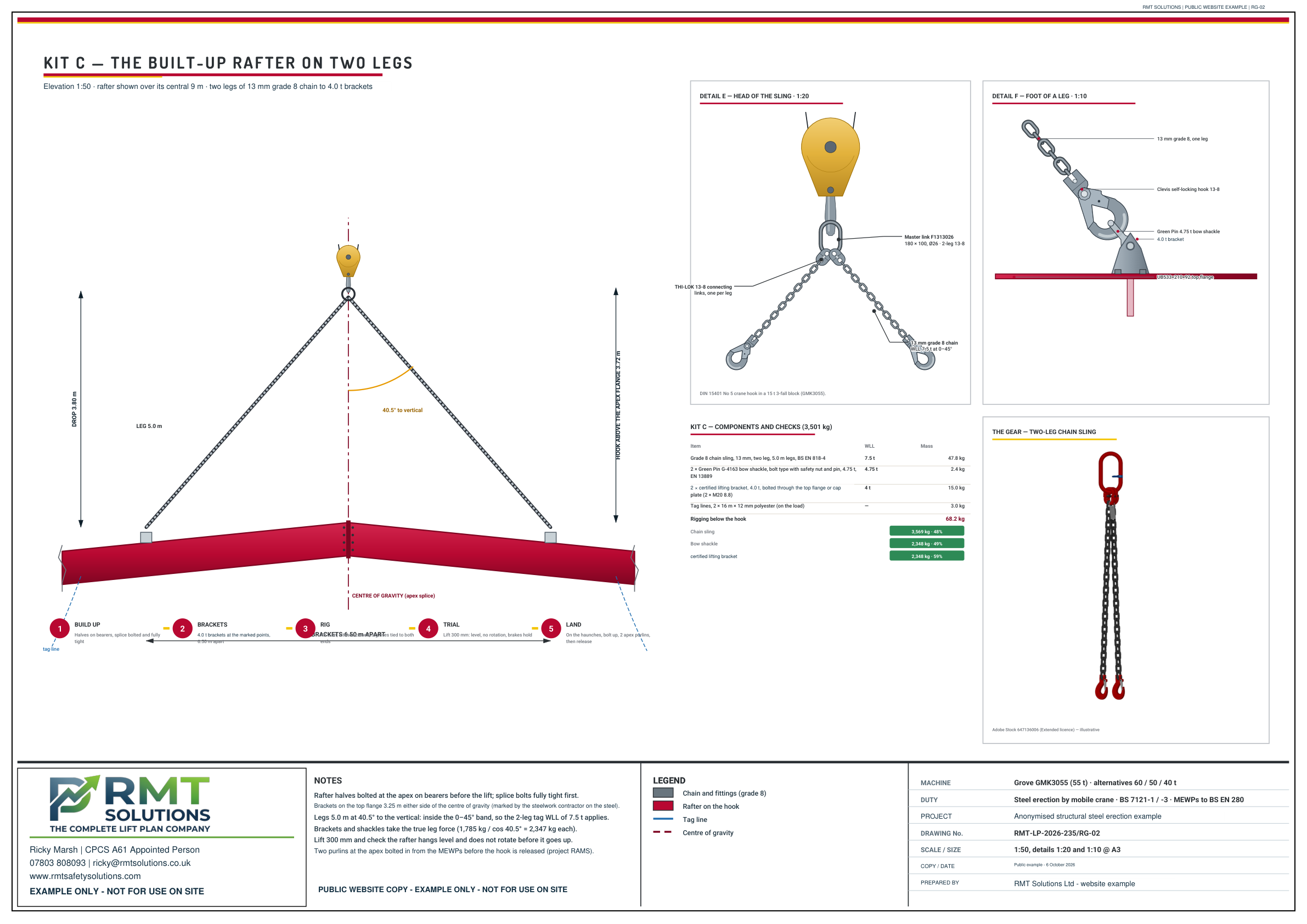
Rafter rigging detail
A supporting rigging drawing showing the proposed lifting arrangement for a steel rafter.
Open full-size drawingThese anonymised drawings show examples of RMT drawing presentation. They are not site instructions or approved plans for another lift. Each operation requires a plan for the actual equipment, load and site conditions.
RMT drawing examples
Transformer installation lift plan drawings
This lorry loader planning example covers the proposed offloading and positioning of two transformer units onto plinths using a Fassi F905R.2. The drawing set brings together the crane and load arrangement, plan view, rigging and lifting-point details so the proposed sequence can be understood and briefed.
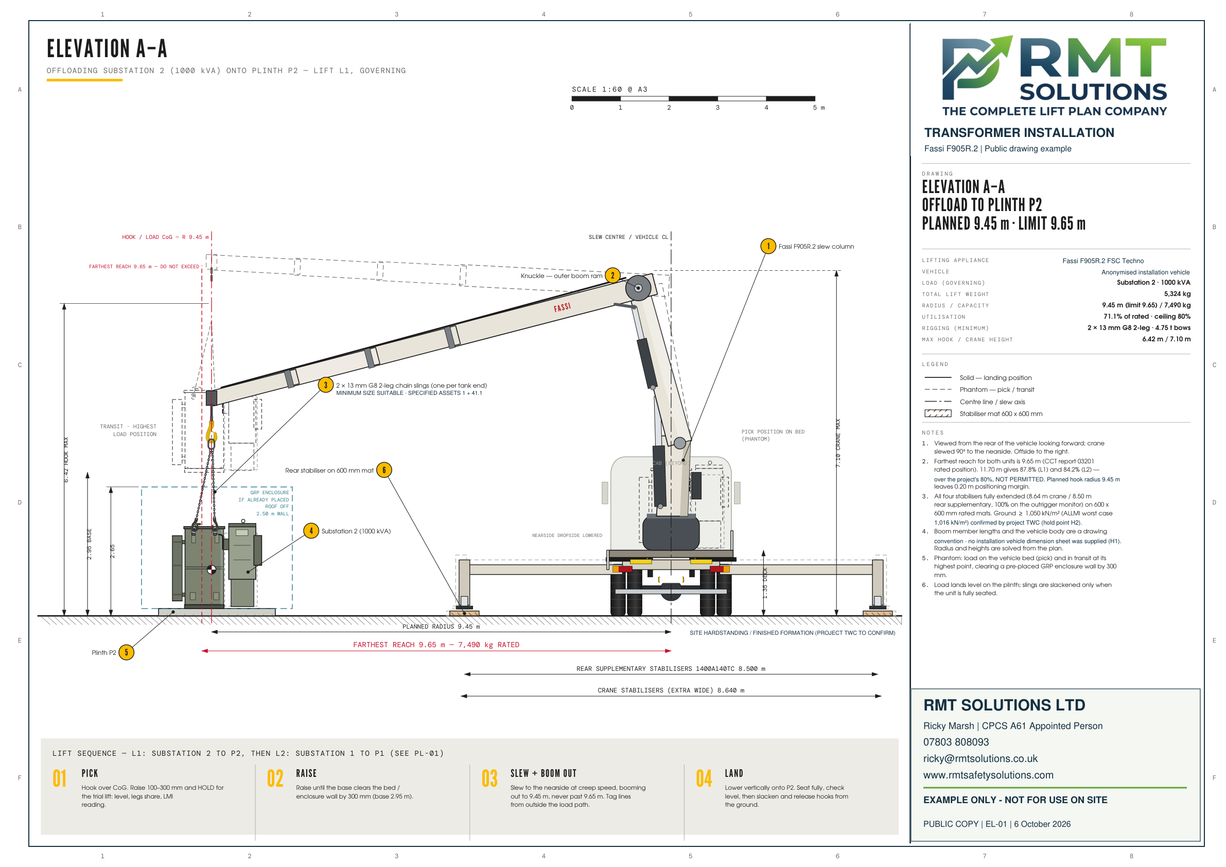
Transformer installation elevation
The elevation shows the proposed Fassi lorry loader arrangement for lifting and positioning the transformer units.
Open full-size drawing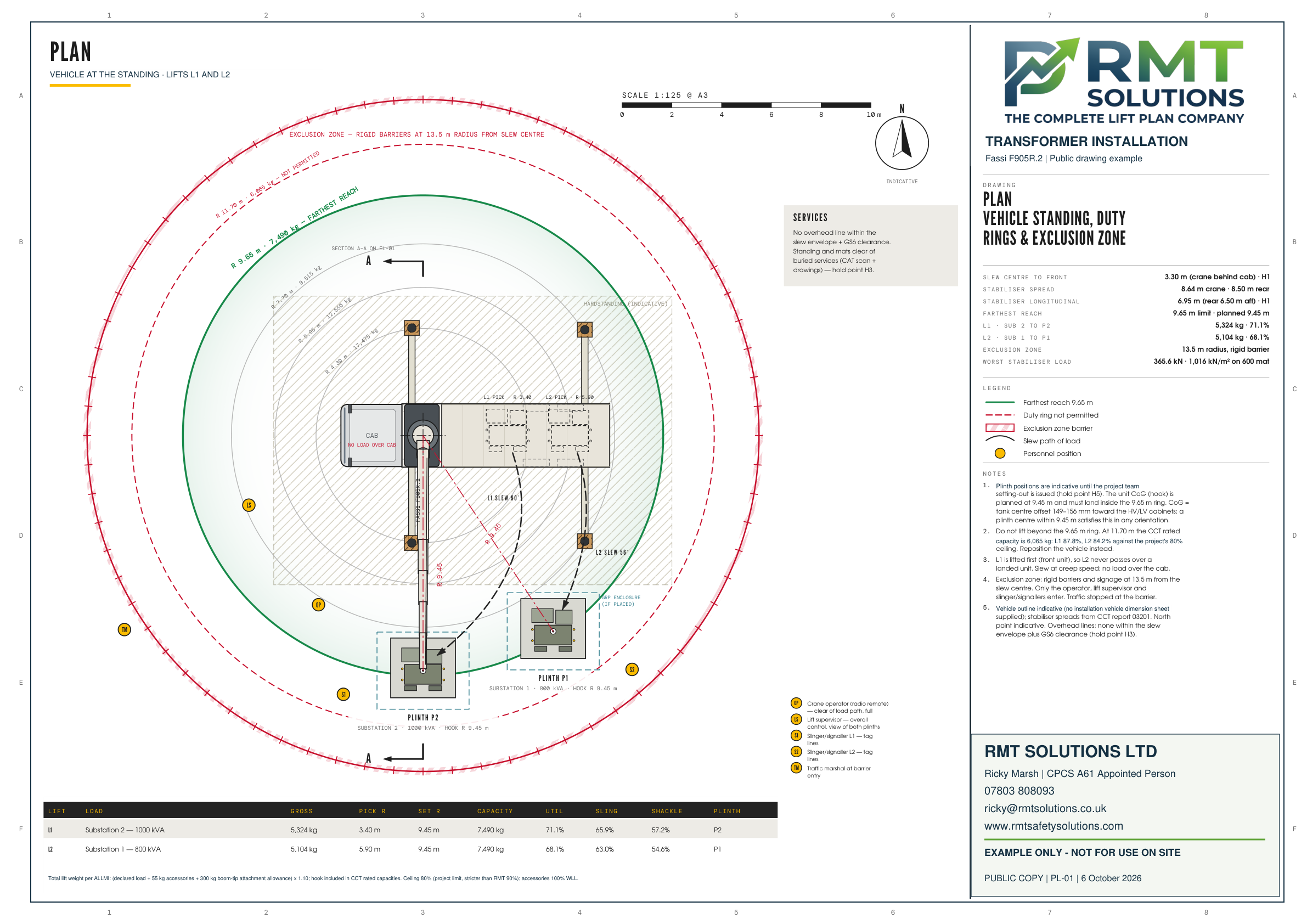
Lorry loader positioning plan
The plan view shows the proposed vehicle, crane and transformer positions for the installation arrangement.
Open full-size drawing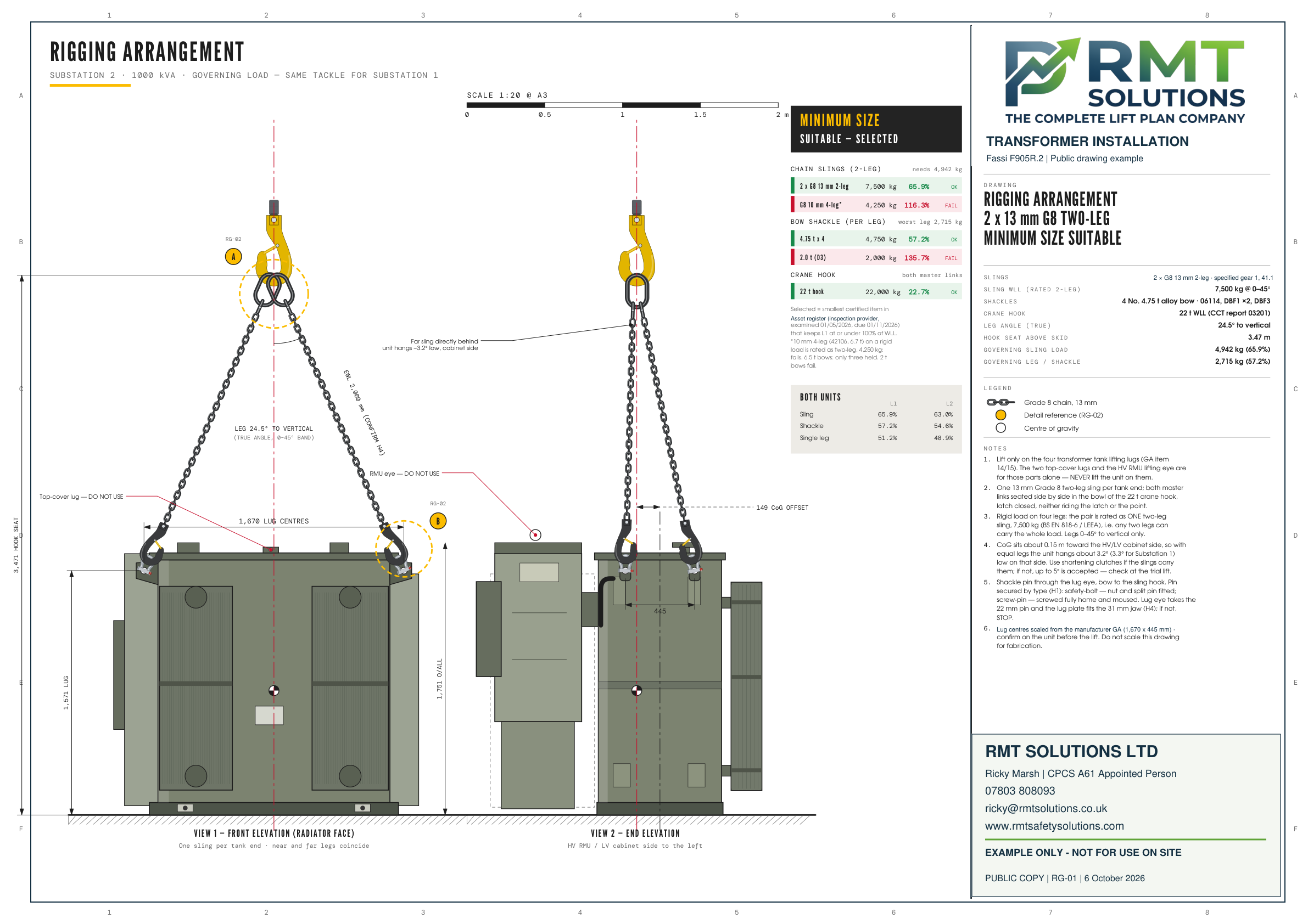
Transformer rigging arrangement
The rigging sheet shows the proposed lifting accessories and arrangement for handling the transformer units.
Open full-size drawing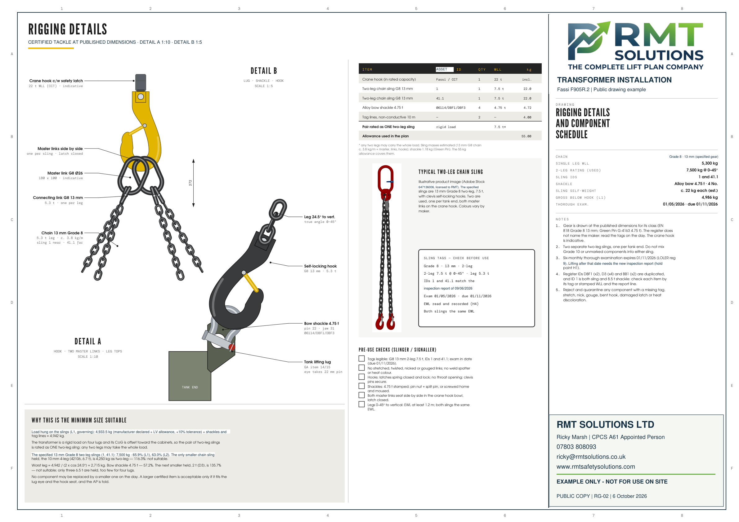
Lifting-point details
A closer view of the transformer lifting-point details supports the proposed rigging arrangement.
Open full-size drawingThese anonymised drawings show examples of RMT drawing presentation. They are not site instructions or approved plans for another lift. Each operation requires a plan for the actual equipment, load and site conditions.
RMT drawing examples
Telehandler lift plan drawings
This JCB 540-140 Hi-Viz example shows how material-handling operations can be presented in a detailed telehandler drawing package. The drawings cover trailer unloading, travel and stacking, scaffold loading bays, wide and special loads, and the unloading and laydown area. They distinguish fork duties from the separately specified hook arrangement.
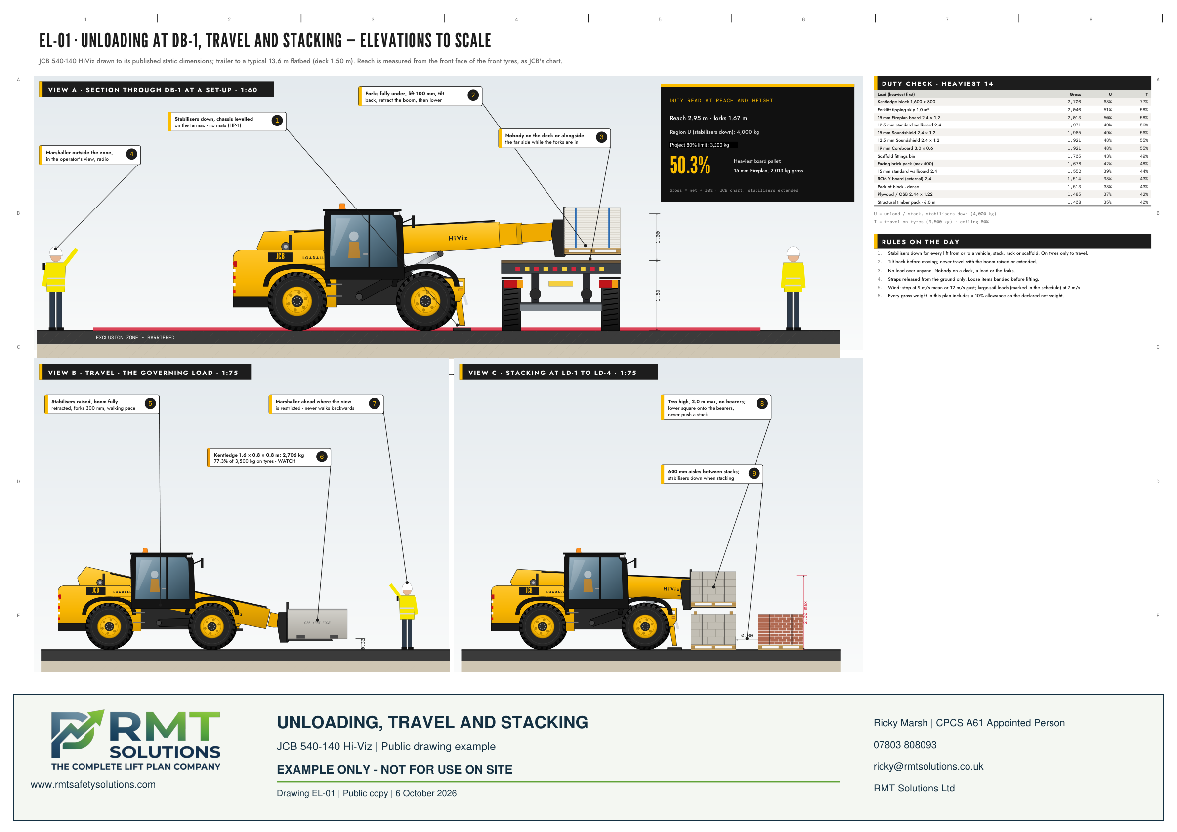
Unloading, travel and stacking
Three elevation views illustrate the proposed trailer-unloading set-up, low travel position and stacking arrangement, with numbered briefing callouts.
Open full-size drawing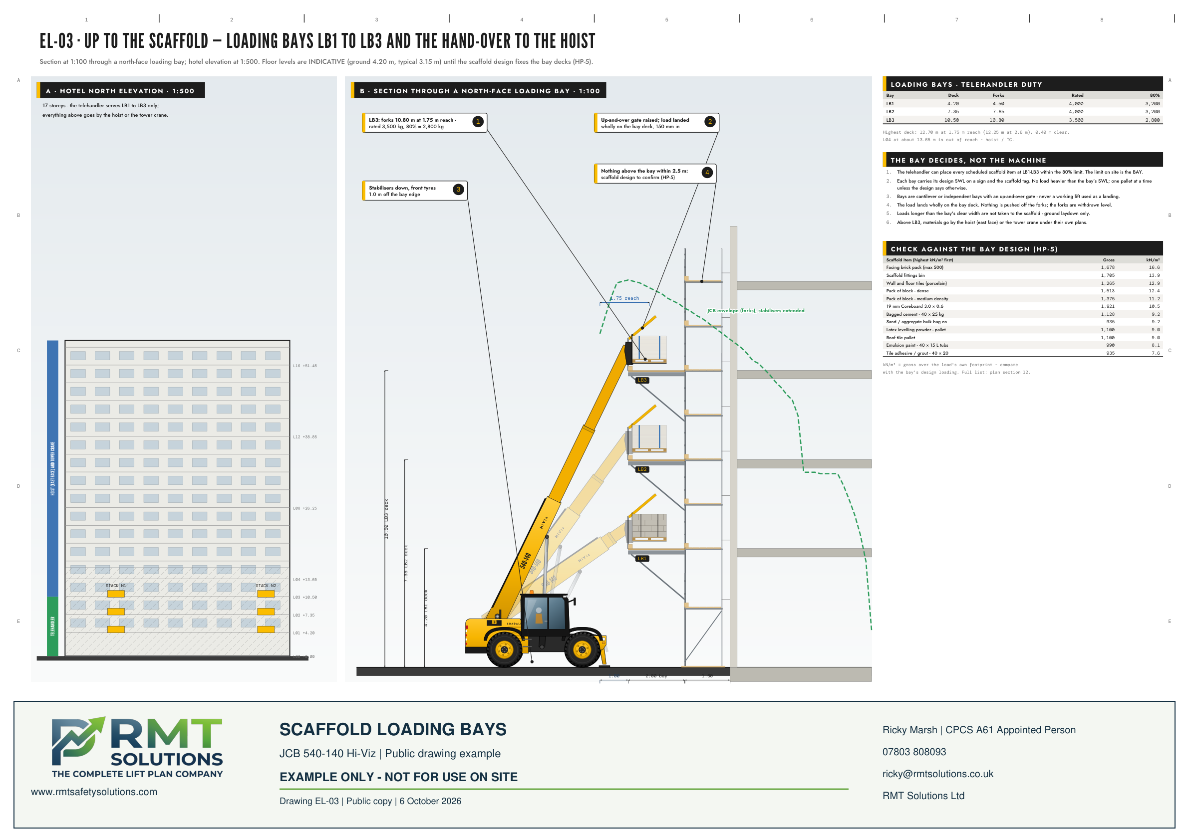
Scaffold loading bay arrangement
The elevation relates the proposed telehandler positions to scaffold loading levels and highlights the need to check the receiving bay design.
Open full-size drawing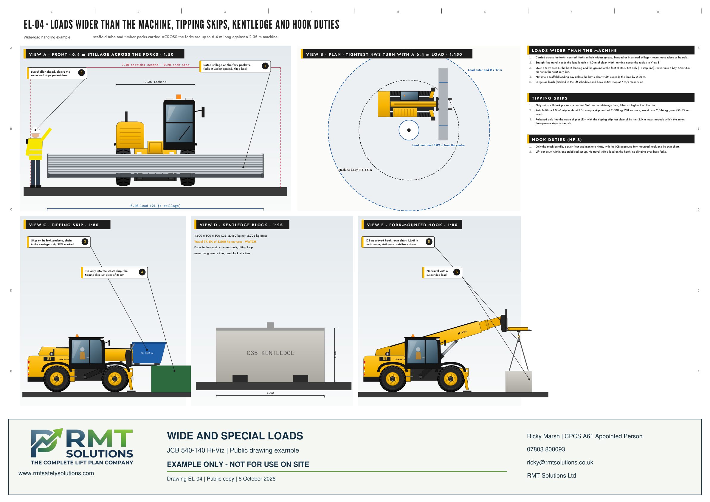
Wide and special loads
Separate views show wide loads on forks, a tipping skip, kentledge and a fork-mounted hook arrangement. Each duty needs its own equipment and load checks.
Open full-size drawing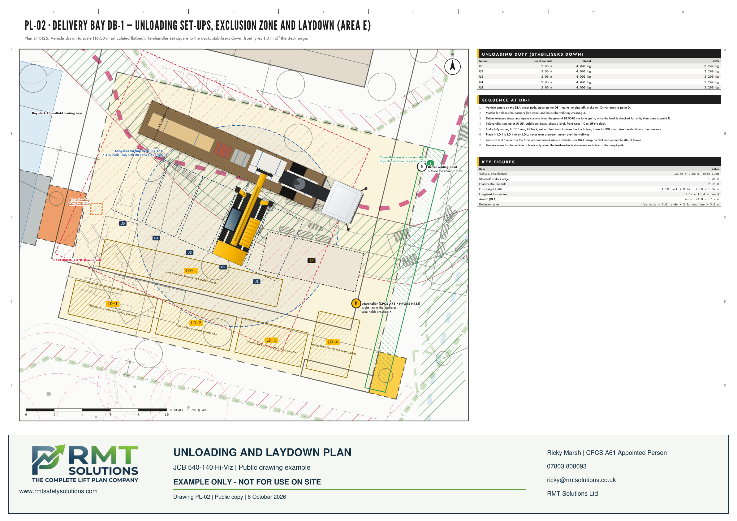
Unloading and laydown plan
The plan view brings together the proposed delivery vehicle, telehandler working positions, exclusion zone and laydown areas.
Open full-size drawingThese anonymised drawings show examples of RMT drawing presentation. They are not site instructions or approved plans for another lift. Each operation requires a plan for the actual equipment, load and site conditions.
What each lift plan drawing shows
Elevation (side view). The machine at the planned radius with its boom or arm solved to the real member lengths, the hook height, the maximum height of machine or load for overhead services, the tail swing and the load at the pick and the set-down.
Plan (top view). The machine footprint, outriggers or tracks, the working radius, the tail swing and the exclusion zone barrier layout, with the slinger, lift supervisor and operator positions.
Rigging drawing. Everything below the hook: the master link, the sling legs at their angle, the shackles and the load's lifting points, with each item's rating and mass and the gross load the duty chart is read against.
3D views. The same lift in three dimensions for the briefing, built from the same geometry as the elevation and plan. They are illustrative; the figured dimensions on the elevation and plan govern.
These are example drawings for fictional or anonymised jobs, marked as examples. They are not site instructions or approved plans for another lift: every lift needs a plan for the actual machine, load and site.